sheet metal bracket design
Sheet Metal Design in 3D CAD
The use of 3D modelling software such as Radan sheet metal software has enabled V and F Sheet Metal to work on simple and complex sheet metal designs without the need to spend a lot of time trying out samples before production. The ability to take a customer sheet metal design in a 3D format such as a STEP or SAT file as well as reducing development time also reduces the risk of translation errors with the sheet metal design before any CNC programming is under taken. If on the other hand a customer doesn’t have a 3D model it’s easy for us to create one which is what we had to do in this sheet metal design example shown here. The design was given to us as a 2D DWG file and we created the sheet metal design in the 3D module and then folded it out ready for programming for laser cutting. All the relevant sheet metal design information such as the material type, thickness, shape, size and bend radii were included in the 3D model to replicate the actual finished component and help the software to develop the correct shape and sized blank.

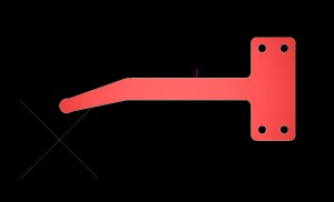
Sheet metal bracket flat blank design
Sheet Metal 2D Flat Blank Design
Once the 3 dimensional sheet metal design has been completed and unfolded a flat or 2D blank is produced. This is then where the computer aided design (CAD) becomes computer aided manufacturing (CAM). We can clean up the design and produce the most efficient tool part around each part. With CNC punching this would be to take the sheet metal design and automatically apply the appropriate CNC tooling for the gauge, internal and external features along with any tags needed to hold the parts in the sheet. With laser cutting, as in this case, the tooling is a continual cutting tool laser beam around the sheet metal design outer profile and it’s 4 holes. This is all carried out automatically by the software with very little intervention from the programmer. Once this stage is complete the part is ready to be nested into a full or part sheet.

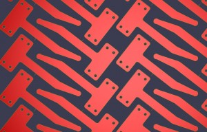
laser cutting nest for sheet metal brackets
Sheet Metal Laser Cutting Nest Design
Now we have to fit the sheet metal design to either a full sheet if the order size needs it or a part sheet or even remnant from a past order. Again the software can automatically select the best layout of components to use the least amount of material whilst running the batch. It can also find the quickest path through the pattern (nest) of components and reduce heat build up when laser cutting. All the orientation of components can be controlled by us to enable parts with a grain direction to be specified or when bending is needed after on a sheet metal design and all parts must run in a certain direction to produce the correct bend angles. At this stage all the codes needed to drive either CNC punch presses or laser cutting machines are generated and saved to the system network server ready to be called up on the shop floor when cutting is needed.

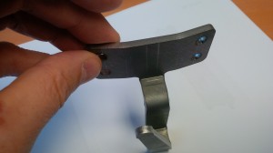
Mild steel bracket
For more examples of sheet metal design and the use of CAD/CAM software take a look at our Pinterest Board
Finished Sheet Metal Design
The final sheet metal design has been transformed into a real useful product, in this case a bracket that is fixed to a leather belt and used to hang a drum for marching bands. The sheet metal design has been taken from a 2D drawing, through 3D modelling, CNC part and nest programming. The mild steel bracket has been laser cut, edge de-burred and CNC bent. The final sheet metal design was then polished and chrome plated by the customer to produce a highly reflective surface finish.
If you have a sheet metal design and you want to discuss some details that you feel we could improve to help with manufacturing and reduce cost please give us a call. Alternatively e-mail your sheet metal design drawings or 3D models to sales@vandf.co.uk and we will be happy to produce some prices for you.