When we sit down to think about a new sheet metal work project here at V and F Sheet Metal we inevitably start by creating a 3D model of the component or assembly we are going to manufacture. Creating a 3D model has many advantages for us and our customers when we are planning to manufacture a brand new design or even an update to a past sheet metal component design. The ability to play with ideas in a software environment without having to commit to cutting or folding any sheet metal materials not only naturally saves time and money but it enables us to investigate different ideas quickly to find an acceptable solution to our customer’s needs and hopefully at a price that is right for both parties. The 3D sheet metal model can be exported and imported back in a STEP or SAT format enabling either our customers or us to initiate the design and update it in a free way until the final design is arrived upon. Some of the advantages of having a 3D model as the starting point for manufacturing are:
3D images to aid communication of the design and understanding of the stages of manufacturing
The 3D model can be used to print out 3D views or wire frame images and dimensioned sections for bending, welding fabrication and inspection of the sheet metal work. These images can be used alongside the customers drawings where needed to communicate complex part details to the workshop to reduce the chances of confusion in production.
Material selection and thickness and its impact on the developed blank size for either CNC punching or CNC laser cutting
The selection of the correct material and its thickness from a customised manufacturing database within the Radan sheet metal software system enables us to automatically create the developed blank to the correct size. As well as having the ability to create this blank size from the 3D model we can check it against the computer controllers on our Safan e-Brake, Trumpf 7036 and Edwards Pearson CNC press brakes. We can check that the correct press brake tooling is used and the impact that will have on the developed sheet metal blank cut size and adjust it on the 3D model if necessary. This adjustment may be needed due to the bend radius of exact material specification used and can be physically checked with a sample piece of sheet metal to prove the design accuracy where needed.
The correct planning of manufacturing tolerances for production processes
The impact of manufacturing tolerance on sheet metal component design is important to achieve the correct fit of parts in our customer’s factories. We have all see drawings with +/- 0.2mm tolerance for a part that is 50mm long and is being CNC punched, which is fine. When the same drawing border is used for a 2000mm long component which is being CNC punched, bent up and welded we have to talk with the customer and investigate what is really important to them and adjust the 3D model where we can so that the sheet metal work produced will still be functional when it comes to assembly.
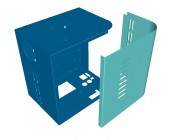
3D software model of sheet metal box and cover (Image A)
The fit of components such as the correct alignment of fixing holes between 2 or more components in any given assembly
As well as achieving the correct tolerance of sheet metal work from the 3D model the actual simple alignment of parts can be checked. The example show here of a sheet metal box and cover is a classic example. The box and cover may be presented to us as 2 separate 2D drawings on a DXG or DXF file or even a PDF image. By creating a 3D sheet metal model of the 2 parts together with the cover in position on the box we can check out for the customer any problems with the hole positions and the correct clearance for the cover to fit allowing for bend radii and powder coating thickness. If there is a problem at this stage it’s much easier to change the design slightly with the customer than manufacture a box and a lid both to the design drawings but not actually fitting together in assembly.
So you can see that the 3D sheet metal model is a great place to start the manufacturing process, play with ideas and basically help our customers where we can before any sheet metal work has taken place. The next stage once the 3D model has been finished is to create the flat 2D developed blank sheet metal part.

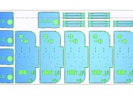
2D sheet metal work blanks (Image B)
Now for us, having Radan sheet metal software enables us to create a 2D blank (Image B) at the click of a mouse button. Not only is the sheet metal model unfolded correctly taking into account all the material type and sheet thickness details from the 3D model but any possible problems are highlighted at this stage as well. If a cut-out or hole is too close to a bend it will be highlighted in a different colour for us so we can take the appropriate action. All the bend lines are also shown on the blank along with the direction and angle of each bend. This data can be useful to the CNC press brake setters and operators when they are programming the press brakes to bend the sheet metal components. We can also add dimensions and notes to the 2D developed blank drawing to enable inspection if required for important features or bend sizes in addition to the drawing from our customer.
At this stage the 2D blank is purely a layout of the sheet metal components to be manufactured and is not machine specific. The next stage is to take this 2D blank and turn it into a part with tooling. For us here at V and F Sheet Metal we have 3 options, either to laser cut the blank with our Trumpf 3030 3KW fibre laser cutting machine, CNC punch with our Trumpf 3000R punch press or our Trumpf 200R punch press.
2D developed sheet metal blanks with machine specific tooling
Once we have the developed sheet metal blank we can select which machine or machines we wish to use to manufacture the component. There may be features in the sheet metal work that mean only one type of machine can be used and then there is no decision to be made. For example a component may have tapped holes, which for us would mean that it would suit our Trumpf 3000R with its tapping head and we would tool everything around this machine. The sheet metal component may have a complex cut-out or profile which we couldn’t easily produce with CNC punch tools or would need special tooling and the batch sizes may only be small so the Trumpf 3030 fibre laser would be the perfect solution. Sometimes the parts are none machine specific such as a 2mm mild steel sheet metal component with round holes and a rectangular outer profile, this type of part could equally be CNC punched with a series of standard tools or laser cut. The big advantage of using Radan software is that the 2D developed blank can be used to tool the part is several ways just with the click of a mouse button. The CNC punch press tooling can be applied to the blank using rules set up in a material database, standard tooling library, preferred tagging methods and standard tooling templates. The laser cutting parts can also be profiled with standard cutting “lead ins” and an automatic tool path calculated to reduce head collision on the laser machine, heat build-up and the shortest route across the sheet to reduce overall laser cutting time in production.
You can see that it is easy for us to create several tooling options for different machines all from the same 2D developed blank so that when the part is in production a range of possible machine options can be chosen to suit the production work load at the point of cutting the sheet metal work.
CNC laser sheet metal part program (Image C)
CNC punched sheet metal part program (Image D)
As an example of this we have included 2 images of the same sheet metal part tooled for laser cutting (image C) and for CNC punching (image D). Each production program would produce the same dimensionally correct components and could be used interchangeably. If a customer preferred laser cutting over CNC punching or vice versa then we would only program one specific way and set up our route card to state which method to use. There is also the advantage of having just 1 blank as the master for different machine tooling options, it enables us to keep all options based on the same issue level of blank and customer drawing.
Once the sheet metal blank has been tooled ready to produce a single part it needs to be applied to a sheet of metal ready for actual manufacture. The pattern of components on sheet can be automatically calculated by the Radan software to achieve the best material yield from any given sheet size and quickest cutting path across the sheet to save time. The sheet used can be standard sheets which for us would be a choice of 3 sizes either 2.0M x 1.0M, 2.5M x 1.25M or 3.0M x 1.5M. If the volume is high enough then special sizes can be purchased in some materials to suit a component length and reduce wastage. For example a sheet metal component blank that is 1.6M long would be wasteful with a 2.0M x 1.0M sheet but would be perfect is we purchased a 1.7M x 1.0M sheet. We can also use up remnants from past work to save buying in fresh material.
Sometimes we have to be able to force the blanks to have a certain orientation on the sheet. This may be ensuring a gained stainless runs the correct way or perhaps the grain of material is important when it comes to bending a component and has been specified by the customer. This is easy and we can control how much automation the software has and how much we need to layout the components by hand if needed to produce the correct nest.

Sheet metal work CNC laser cutting nest (Image E)
The laser cutting next show here in red (Image E) are of thin gauge aluminium parts that were not bent and had no grain effect on the sheet so we were free to get as many as possible from a sheet of metal. You can see that the software is able to use a true shape nester to fit parts inside each other’s profile where possible to get the best use of material. We can also select to tag the parts into the nest if needed of allow them to just lay on top of the bed for ease of collection after cutting.
There are some decisions to be made when it comes to which gas to use when laser cutting the sheet metal work. The options with our Trumpf fibre laser cutter are nitrogen, oxygen or compressed air as the cutting assist gases. The nitrogen comes direct from a tank where liquid nitrogen is converted to gas, the oxygen direct from banks of bottles and the compressed air from a dedicated air compressor. The choice of gas is dedicated by the types of material being laser cut, the thickness of the material, the final treatment or finish applied to the sheet metal work and the quality of cut required. The software makes the decision which gas to use based on a set of rules but we can change the gas if that is an option that the laser cutting machine can use.
All the compiling of code to drive the laser cutting machine is generated with the click of a mouse and saved automatically to our system server ready for the laser cutting machine setter to call up when they are ready to laser cut the parts.
The selection of material sheet metal type, thickness and size is exactly the same as that described above for laser cutting. The CNC punching machines that we have can CNC punch up to 6.35mm thick but we tend to stop at around 4mm and move thicker work to the laser cutting machine.
The only limitation that we have with CNC punching that doesn’t apply to laser cutting is the need to clamp the sheet so that it can be moved in an X and Y axis. With the laser cutting machine the cutting head of the laser moves across the sheet in an X and Y axis and the sheet sits still on the bed but with the CNC punch it’s the other way around with the head being fixed as part of the frame of the machine and the sheet being moved in an X and Y direction.
The sheet is clamped on the X axis rail with a minimum of 2 clamps. This constrains us to a panel that needs to be big enough to get 2 clamps on and the components we are going to CNC punch. Again as with all the processes that have come before this point we can experiment with different sheet sizes and shapes to work our which will best suit the components being CNC punched and the batch size needed to satisfy the customer’s order quantity.
A nest can be produced for more than 1 component so that a family of parts could be CNC punched together for example a box and its lid or perhaps right hand and left hand side panels. The advantage of this method of CNC punching is to manufacture sheet metal work from the same material making it easier for the set up and bending with material conditions being the same. There is also an advantage for production planning with associated metal parts be run together.
Sheet metal work CNC punching nest (Image F)
This method of CNC programming can be used to get the best from a sheet if parts that are from different orders and possibly from different customers but are using the same material and thickness and can be placed together on a sheet saving set up time. The CNC punching nest (Image F) here again illustrates our box and other parts that were needed or the same order being set together as a kit of parts.
Some of the parts have been placed close enough together that a single slitting tool can punch out the left hand side of one while punching out the right hand side of another, this is known as common line cutting. We normally use this method of cutting sheet metal work to help reduce the amount of punch strokes the punch presses takes to produce the parts in the nest and to save materials. It’s easy to produce this effect with rectangular and square shapes but not as easy with other shapes although some can be common line punched with a little thought and time. As with all these programming methods there is a balance to be struck between the speed of which the automatic nest the software can produce and the “improved” nest that the operator can produce is worth the time to produce. If you only have a small volume of sheet metal parts to produce or it’s just a special one off order it would not be worth fine tuning a nest. If however the nest is for a large number of parts or a part that is going to be commonly produced then a little time may well pay dividends in reduced CNC punching time and reduced material usage.
At this stage it’s worth mentioning that the holes pierced or punched into the sheet metal are produced with a punch, stripper plate and die. The clearance of the die is important when being used with any given punch and the thickness of material. Generally the thicker the sheet then the larger the die clearance needed for a certain punch size. For example, a 10mm square punch would need a 10.2mm square die for 1mm mild steel but this could increase to a 10.4mm or 10.6mm die for 2.5mm or 4.0mm mild steel. The punch will stay as the original 10.0mm square for all the material thicknesses. This increase in die size enables the punch to push the extra material through but exaggerates the draft of the hole sides in cross section, the 10mm punched square hole would become 10.0mm across on the top of the sheet and 10.2mm on the bottom or die side of the sheet. You can see that this is increased as the material becomes thicker with some dies producing 0.6mm extra across the hole.
The use of CNC tooling is very efficient with a Trumpf single head machine compared to turret punch presses. On a Trumpf, every tool can be rotated through 360 degrees enabling each tool to do more work and be free to move to any position necessary to produce some very complex sheet metal work when needed. I will talk in more details about the exact type of tools and their uses when I talk about CNC punch presses. It’s enough to just know that we have total control over which CNC tools to use, which order to apply them to the nest and the ability to try out different orders and patterns to see which will be best when it comes to actually punching the sheet metal work. As with laser cutting once all the parts have been laid out correctly, tooling organised and the correct order of punching chosen the codes can be produced and complied to drive the relevant CNC punching machine.
Whether a part is going to be laser cut or CNC punched it has had a 3D model created, developed 2D blank produced, a single part tooled and a nest of parts prepared for manufacture. Now the software can be used to produce the actual sheet metal work using our manufacturing plant.
I discussed the options that were open to us when programming to select a gas to assist the laser when cutting sheet metal work. To recap we have the choice of nitrogen, oxygen and compressed air as the gasses that can be used to laser cut sheet metal work.
Here is a list of the gases we can use and the most common materials that are laser cut. You may be surprised to see brass and copper alloys mentioned in this list as they are not commonly laser cut but with a fibre laser cutting machine they are not an issue right up to 6mm thick.
Mild Steel
Up to 1.2mm thick = compressed air, nitrogen or oxygen
Up to 6.0mm thick = nitrogen or oxygen
Over 6.0mm thick = oxygen
Zintec or galvanised coated mild steel
Up to 1.2mm thick = compressed air or nitrogen
Up to 3.0mm thick = nitrogen
Stainless steel alloys
Up to 0.9mm thick = compressed air or nitrogen
Over 1.2mm thick = nitrogen
Spring stainless steel alloys
Up to 0.9mm thick = nitrogen
Aluminium alloys
Up to 1.2mm thick = compressed air or nitrogen
Up to 12.0mm thick = nitrogen
Copper alloys
Up to 6.0mm thick = oxygen
Brass alloys
Up to 6.0mm thick = nitrogen
The bed of the Trumpf 3030 can take sheets up to 3M long by 1.5M wide which is a sheet size up from the CNC punch presses that can take 2.5M long (without a reposition) by 1.25M wide. The extra size is advantage when it comes to laser cutting large items of sheet metal work and when cutting smaller parts. The more parts we can get on a sheet the fewer times the laser machine has to stop while a sheet is being changed and so the more cutting time per hour we can achieve. The sheets of material are laid on an automatic pallet changer unit that allows a sheet of metal to be laser cut while another is being prepared for cutting or a previous sheet is having finished parts removed from the bed.

Trumpf 3030 fibre laser cutter cutting mild steel sheet metal brackets (Image G)
As there are no tools on the laser only a nozzle that is changed between different gauges it allows a very quick set up time between different jobs. A sheet can be placed on the pallet changer, nozzle swapped over if needed and program loaded in just minutes. This enables us to try out parts quickly or cut extra parts if needed without any real impact to a production plan.
Image G shows some 1.5mm mild steel sheet metal work being laser cut. The first 3 parts have been removed to check the holes sizes are correct to drawing before running the batch of parts. The machine setter has the ability to fine tune the laser to offset any errors and produce the correct sheet metal component size.
And here’s the laser cutting machine actually cutting out these mild steel parts.

Laser cut mild steel sheet metal work (Image H)
Using a laser cutting machine to produce sheet metal work can be very flexible. Not only can the laser cutter cut out small holes, complex shapes and straight lines it’s great at cutting larger circular holes and outer profiles. The parts shown in Image H have been laser cut from a thin gauge mild steel and the circles are absolutely perfectly round and with a smooth clean edge on both sides of the sheet. Round profiles like this can be produced with custom made banana tooling on a CNC punch press but not with the same edge quality or the same lack of evidence of the cutting process. Because the setting time is so quick on the laser there is less impact on price for a reduction in batch size with the result that small batches of sheet metal work on the laser can be produces at similar prices to higher volumes.
When we CNC punch sheet metal work we have to think no only about the component we want but also the sheet metal that is left which is known as the skeleton. The tools needed to punch out the correct part will have been selected in the programming phase of production and these will be available to the machine setter. The program will also control the order in which the punching is to take place so that any features such as a ventilation louvre is not then damaged when CNC punching say the outer profile. The tag size that the part is held into the sheet skeleton will also have been programmed in so that the parts should stay in the sheet right until the end of the program but the tag is small enough to enable the parts to be easily removed from the skeleton without damaging the edge profile. Depending on the part’s size, shape and finished surface quality requirements a CNC punched part could either be tagged in the skeleton as shown here, designed to drop down through the machines chute into a collecting bin underneath after its last punch operation or for the machine to stop and allow the operator to take each part out by hand.

Trumpf 3000R CNC punch press punching out 0.9mm mild steel sheet metal work (Image I)
The back rail, which can be clearly seen in Image I, holds all the tooling that is needed for the program being produced. The clamps are also held on the back rail and can be seen clamping the 2M x 1M sheet of Zintec. As well as having individual tooling in each tooling location we make use of special tooling know as multi-tool holders. On the Trumpf 3000R there are 2 multi-tool holders and each hold 10 sets of the most common small round sizes from 2.0mm to 8.0mm. These multi-tool holders greatly increase the total tooling held on the back rail, reducing the amount of tooling that needs to be set when changing jobs and enabling very complex sheet metal work to be punched in one programed operation. On the Trumpf 200R we have 3 multi-tools with 6 stations in each to perform the same task of reducing the amount of tooling setting needed through the day.
When a pattern of many holes is needed again and again a tool known as a cluster tool can be used with a series of punches and a die with a pattern of holes to reduce the amount of hits required to make a component. This is particularly helpful when CNC punching arrays of holes for ventilation patterns.
The Trumpf 3000R CNC punch press can also use some specialised tooling to increase the flexibility and productivity of the sheet metal punching process. These tools include:
Multi-shear = a special slitting used on long runs to produce a sheet metal parts with an edge without any signs of CNC nibbling. This is particularly useful when CNC punching front panels for electronics equipment.
Multi-bend = a tool that can produce bends up to 40mm long and 20mm high within the sheet eliminating post punching bending work.
Tapping heads = a range of tapping heads can be used to allow the head of the machine to form a thread after a pilot hole has been CNC punched in place. The speed of the head usually allows a thread to be formed without any swarf being produced in 1.5 seconds.

CNC punch press engraving (Image K)
CNC engraving = a stylus tool can be used which vibrates up and down inside the punching head at a very fast rate to make a single mark in the top surface of the sheet. By moving the sheet metal around on the bed of the punch press the marks can be joined together and create a continue line. Using the tools within the programming software the machine can be made to engrave company logos, instructions or part numbers such as that shown in Image K. This example is in aluminium and has been black anodised but we have manufactured panels that have been engraved in this manner and then powder coated and the engraving is still visible.
All these tools are used to reduce production time and improve the quality of the sheet metal work being produced.
Video of sheet metal lighting geartrays being CNC punched with their internal windows dropping through the machines bed and into a tin below. The punch press is also using “banana” tools to produce the outer curved profile. Take a look at the next video below to see the same gear trays being folded up.

CNC punched sheet metal work from 0.9mm Zintec (Image J)
The sheet of zintec components shown in Image J have been CNC punched out of a 2M x 1M sheet 0.9mm thick. As well as some standard hole details the components shows some other interesting sheet metal work features that have all been CNC punched. There is the general curved outer profile to the shape which has been achieved by using “banana” tools. The tools are ground to the correct radius for the component needed and can be rotated in the head as the CNC punch press works its way around the circle. They are easy to use, much quicker than trying to “nibble” out the circle with a small rectangle tool and they produce a clean edge profile second only to laser cutting. At 2 ends of the component there are rads on the corners and these have been punched into the sheet with a radius tool with R2, R3, R4 and R5 all on one tool. We simply use whichever rad is needed for the component design making it easy to produce the correct corner radius. There are plunges in the design as well which have been formed into the sheet. These plunges are formed after a pilot hole has been punched in position and can be used to take a self- tapping screw giving more wall thickness locally for the screw to bite into. Again on this nest you can see how well the parts are interlaced to save material in production.
So we have our developed and cut sheet metal blank whether it has been laser cut or CNC punched, now we have to turn our attention to any bent form that the sheet metal work may have.
We have 6 CNC press brake bending machines in our sheet metal work bending area. I will talk about the Trumpf 7036 and the Safan e-Brake machines on this page but there are other machine too that are covered in more detail in the plant pages section of the web site.
We have 2 Trumpf 7036 machines and they are the same specification and work right next to each other, sharing the same tooling and CNC programs. The machines basic specification is to bend sheet metal work up to 1M long and with a maximum of 36 tons force, they are all electric powdered and very fast. The ethos behind the machines is to be quick to set up, accurate and very fast to bend the small components in our work shop.

Trumpf 7036 CNC press brake in the process of bending sheet metal work (Image L)
We have so many small sheet metal components to fold up that these machines are just perfect, Image L shows 1 of the machines with a typical sheet metal component being bent. All the CNC programs can be created on the machine controller and saved directly back to our system server, allowing for recall of the programs for future batches and running on either machine. If a large batch of sheet metal work is needed we can set the tooling and programs in both machines and double up our production rate across both machines.
A CNC press brake basically controls 2 bend tools to come together and make a bend in a piece of metal. The top tool is traditionally a V blade or punch and the bottom tool is a V block or die. The angle of any given bend is achieved by increasing the distance that the top tool enters the bottom tool and with the air bending style of tools that we use some parts can have internal bend angles of 28 degrees. If an internal angle is required tighter than this we use a flattening tool to press the two sides of the bends together until they touch if needed which becomes a safe edge or Dutch fold. The length of a bend is determined by a pair of computer controlled back stops, the further out the back stops travels from the bend tools the deeper the bend will be. We have a range of different tools to suit different material thicknesses and to achieve different bent radii. The Trumpf style tooling on these machines is common to our much larger Safan e-Brake CNC press brake enabling us the ultimate flexibility of moving jobs across the 3 bending machines when needed to help if there are bending bottlenecks or if a machine is being serviced.
By programming a series of bend angles and bend depths complex sheet metal work can be bent up. Using the computer control to create the part in 3D on the machine enables the machine programmer to simulate the finished part, tooling requirements, the correct bend sequence and cut size. The cut size can be used to verify the developed blank size from the 3D model if required to check all the calculations are correct before any materials are cut.
Video of the Trumpf 7036 CNC press brake in action folding up lighting gear trays.

CNC folded sheet metal work with multi-bend techniques (Image M)
I have included an image of 2 curved sheet metal profiles that work together to deflect air in an air conditioning system, see Image M. All the bends and the curves have been created on the Trumpf 7036 machines using just standard press brake tooling. The curves have been created by using a bending technique called multi-bending or bumping. The curve is divided into a series of slight bends and flats so that the curve is created as an approximation by flats at a tangent to the desired curve. The closer each bend is together the better the finished curve will look but the longer it will take to bend the sheet metal work. There is normally a compromise between the finished shape and the time spent bending which will affect the costs for the customer. The advantage of this type of bending over say having a special form tool made is the ability to change the curved profile whenever the customer wants to update a design without any tooling costs, just a few minutes with the control software is all that’s needed.
Our Safan e-Brake CNC press brake is the latest addition to our bending facility here at V and F Sheet Metal. It was installed in June 2015 and replaced an old Edwards Pearson PR6 CNC press brake that had done a brilliant job for nearly 20 years. The old Edwards Pearson machine was a 2.5M long 60 ton hydraulic machine and was good for most of the longer sheet metal work that we needed to bend for many years. Once we had installed our new Trumpf 3030 laser cutting machine in 2013 we had the capability to laser cut sheet metal work up to 3M long so it was inevitable that we would need to fold sheet metal components up to 3M long as well at some point. The Safan e-brake not only gave us that extra length but it also has 100 tons of force, enabling us to bend thicker parts from the laser as well. The Safan is all electric expect for automatic hydraulic top tool clamping which enables it to run very quietly in production and very fast. A machine setter/programmer can draw a component’s cross section on the screen with their finger and then add dimensions to create a bending program, see a 3D image, simulate the bending sequence and select the correct tooling for the material type and thickness. A with the Trumpf 7036 machines they both have lighting built into the front of the machines to enable the operator to clearly see what they are bending and to align sheet metal work correctly up against the back stops.

Safan CNC press brake (Image N)
Again as with the Trumpf 7036 controller the Safan e-Brake (Image N) can be used to calculate cut sizes and check these against the 3D models software developed blank size for accuracy.
Here is a nice example of the Safan e-Brake in action bending up some 1.2mm thick brass sections into boxes. You can clearly see the top V tools and the back stops in position at the correct position to measure the depth of the bend required. The bottom V tool is covered in a thin layer of a special plastic that is helping to prevent and bend marks appearing on the outside of the boxes during bending.
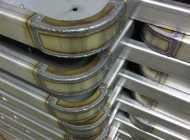
Folding brass components (Image O)
Folded sheet metal work (Image P)
You can also see from Image O that the Safan e-Brake has a large opening between the top beam and the bottom bend enabling us to fold deep boxes and sections with standard tooling. There is also an image of the final folded box (Image P) which had a couple of small tack welds to complete it before being cleaned up and sent off to the customer. The brass boxes were used for mounting door entry panels on blocks of flats.
Once we have folded up our sheet metal work it often needs to have bushes and studs inserted as one of the last stages of manufacturing.
Many of the parts that we manufacture need to have male and female threads permanently pressed into place within their design. They may be self-clinch studs or bushes or the Hanks style anchor rivet bushes. We press in millions of bushes and studs of all sorts of styles, materials and sizes every year in a vast range of sheet metal work. By cutting or punching the correct hole size the insert can be easily positioned accurately in the component and the part securely pressed into place either using our Haeger Inserter of one of our fly presses.

Sheet metal work with studs (Image Q)
Both options work well whether we are pressing in stainless steel studs, aluminium stand-offs, mild steel and zinc plated hank bushes or a range of the more specialist inserts that can be pressed into sheet metal components. Image Q shows some laser cut mild steel plates with M4 x 20mm long studs pressed in place. There are so many different types of insert that whole websites are dedicated to them so I will not try and go into too much detail here.
For more details on the full range of parts that can be inserted we are more than happy to advise you if you send us your drawings to sales@vandf.co.uk or call us on 01489 577786.

Fly press tooling (Image R)
Fly presses are simple machines that enable us to work with sheet metal in a wide range of ways. The fly presses that we have here have been converted to use hydraulic power packs and can have up to 9 tons for pressing force which is more than enough for the smaller sheet metal components that we put through them. The fly-presses can be used to bend up wire and bar as the Image R shows, fold small sheet metal parts, flatten our parts with stress induced bow from CNC punching, pierce holes, press in bushes and studs, form dimples in plates, run small die set press tools to make production batches of small items and a host of other operations.
The advantage of using fly presses is their simplicity. We can make up simple tools and try them out in the fly presses without a lot of cost which is ideal of small batches of work or where a customer isn’t quite sure whether their design is right and wants to try things before committing to full tooling options in production.
Welded sheet metal work (Image S)
We can weld sheet metal work in mild steel, Zintec and galvanised mild steel, stainless steel alloys, aluminium alloys, brass and copper. We use tungsten inert gas (TiG), metal insert gas (MiG) and gas brazing for range of materials. These welding techniques allow us to tack weld, stitch weld, seam weld and puddle weld a range of different designs and material thicknesses. The exact design of corners in folded boxes, trays and fabricated assemblies can be arranged within the 3D model to create a weld preparation area to produce the right amount of weld penetration. The majority of the welding that we carry out is of a cosmetic nature so is often cleaned off using hand tools to produce a smooth outside surface ready for painting or powder coating so that the final sheet metal work doesn’t even look as though it’s been welded. Image S is a good example of TiG welded stainless steel fabrication.

Sheet metal welded fabrication (Image T)
Once all the welding has taken place on a certain part or assembly of parts any cleaning up and smoothing off of the welds can take place. We use a range of hand held grinders, orbital sanders, electrical and air operated to work with the welds. Using a range of different disc grades and media we can go right down to smooth joints the same as the parent metal. The example show in Image T is of an aluminium enclosure that has been bent up, welded and cleaned off smooth with the final finish achieved by orbital sanding. The enclosure was then powder coated and no signs of the welding and cleaning up was visible through the powder surface.
As well as cleaning up welds we have a range of de-burring machines that we use to remove any unwanted edge burrs that might be present on sheet metal work after its been laser cut or CNC punched. I have included a video below of a round mild steel disk being de-burred with a vertical de-burring belt machine.

Spot welding sheet metal work (Image U)
Another form of jointing 2 of more pieces of sheet metal together with a permanent joint is to spot weld. The spot welders (Image U) we use are rated up to 30KVA and are more than capable of spot welding the thinner gauge sheet metal work that our customer want joining together. The joints want be achieved much quicker than Tig or MiG welding and they are smaller and neater but not as strong. To counteract their relative weakness when compared to TiG or MiG welding we apply more spots to a joint to create the correct strength needed. We can spot weld mild steel, zintec and galvanised mild steel and stainless steel. We can spot weld thin aluminium sections but the results are not as reliable as they are with ferrous materials.
There are other sheet metal manufacturing processes that we carry out here including rolling, drilling, sawing, press work, guillotining, stud welding and tapping treads but the vast majority of the sheet metal work we produce use the processes listed above.
Once we have our sheet metal work finished it can be shipped self-colour or it might be treated or finished with certain processes to protect its surface or improve its cosmetic appearance, I have listed a range of the common finishes below and some examples are shown in Images V to Y.
Black anodised sheet metal work (Image V)
Alocromed sheet metal work (Image W)
Zinc plated sheet metal work (Image X)
Powder coated sheet metal work (Image Y)
Anodise – aluminium treatment (image V)
Aluminium sheet metal work can be anodised to provide an aluminium oxide surface that is clean and cosmetic. The anodised parts can be left a natural aluminium silver colour or they can be dyed as these black angle brackets. The bushes and studs have to be inserted after anodising and show up here as a silver (mild steel and zinc plate) colour.
Alocrom and Iridite – aluminium treatment (image W)
Aluminium sheet metal work can also be treated by a method of dipping in a chemical which converts the outside surface, sealing it from corrosion and enabling a good earth contact which can be important with electrical equipment. The commons options are alocrom 1000, alocrom 1200 and iridite NCP treatments.
Zinc pate – mild steel treatment (image X)
Mild steel sheet metal work can be zinc plated and either clear or colour passivated to protect its outer surface from corrosion in normal environmental conditions.
Powder coat and wet spray painting – all metals finishing (image Y)
Ferrous and non-ferrous sheet metal work can be powder coated or wet spray painted not only to protect the surfaces from corrosion but also to produce a good cosmetic finish. With a large range of standard colours, gloss levels and surface effects including metallic finishes it’s a very popular way to finish off sheet metal work.
In conclusion I hope you can see by now that the term sheet metal work can cover such a wide range of processes and product designs. From the simplest flat metal plate to complete fabricated sheet metal assemblies such as 19” rack equipment enclosures, sheet metal can be a solution. By constantly investing in new manufacturing technology, tooling and software we are always looking to improve the quality of the sheet metal work we produce and maintain the prices offered to our customers by using more efficient working methods. With the wide range of material types and thicknesses that we can laser cut, CNC punch, CNC bend and weld we offer a comprehensive service to our customers right across the UK. Be it just a few aluminium boxes with covers, a couple of hundred stainless steel pump mounting brackets to thousands of electronics front panels we will have a solution using sheet metal. Alongside a wide network of platers, painters and machining companies V and F Sheet Metal can offer you the complete sheet metal work manufacturing service.
For more details please take a look at our website plant list, design ideas pages, CNC punch press standard tooling library, and galleries of past sheet metal projects and of course our busy blog on the latest sheet metal work that we have produced to our customers designs.
If you have a specific need the please contact us